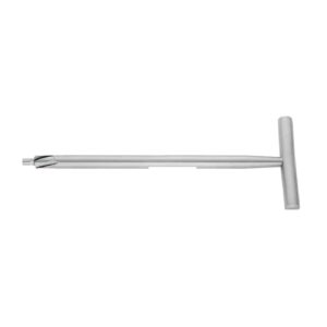
Depth Gauges, Taps and Drill Guides in Fracture Fixation
How surgical depth gauges, bone taps and drill guides work in fracture fixation, with AO drill and screw pairings plus inspection criteria.
A 4.5 mm cortex screw sits 3 mm proud of the far cortex on a distal femur plate. Nobody notices in theatre. Six weeks later the patient presents with anterior knee irritation and the screw comes out under a second anaesthetic. The plate was fine. The reduction was fine. The measurement was wrong.
Screw length is one of the few things in fracture fixation that is decided entirely by a hand instrument, and the hand instrument in question is usually taken for granted. Depth gauges, taps and drill guides are the unglamorous middle of every plating set — they never appear in the marketing photographs, and they are the parts that most often come back to us bent, worn or missing a hook tip.
This guide covers what those three instrument families actually do, how they are dimensioned against the AO screw system, and what to inspect when you are buying or reprocessing them.
Why Screw Length Errors Are More Common Than Surgeons Assume
The published data on measurement accuracy is sobering. In a study of depth gauge readings against known drilled hole lengths, mean accuracy was around 57% for senior surgeons, 42% for intermediate grades and 31% for juniors. Accuracy dropped further with angled drilling in diaphyseal bone — roughly 33% — because the gauge hook no longer sits square against the far cortex.
The clinical consequence is not trivial. Screws left long enough to tent or abrade adjacent soft tissue are associated with tendon irritation and rupture in a reported 12–23% of affected cases, with the extensor pollicis longus over a volar distal radius plate being the classic example.
Two mechanisms account for most errors, and both are instrument-related rather than surgeon-related:
- Under-reading — the hook has not truly caught the far cortex. It sits inside the medullary canal or catches a spicule of cancellous bone. The reading is short, the screw is short, and purchase in the far cortex is lost.
- Over-reading — soft tissue, periosteum or a fragment of drilled debris is trapped between the gauge barrel and the near cortex. The barrel stands off the bone and the reading is long.
A worn or bent hook tip makes the first failure mode far more likely, which is why hook geometry is the single most important thing to inspect on a used gauge.
Drill Guides: Neutral, Load and Threaded
The drill guide’s job is to place the hole where the plate hole wants it, at the angle the construct requires. In conventional (non-locking) plating there are two guides that matter.
Neutral (Green) Guide
Centres the drill in the plate hole so the screw head seats in the middle of the oval. Used when no compression is wanted — buttress constructs, bridging plates, and any hole where the fracture is already compressed by another screw.
Load / Eccentric (Gold) Guide
Offsets the drill away from the fracture, typically by around 1 mm on a 3.5 mm dynamic compression plate. As the screw head descends the inclined ramp of the DCP hole, the bone travels toward the fracture and interfragmentary compression is generated. On a standard DCP a single eccentrically placed screw yields roughly 1 mm of travel; a second load screw from the opposite side adds a similar amount.
Threaded LCP Drill Sleeve
Locking plates change the requirement entirely. The sleeve threads into the plate hole so the drill trajectory is fixed by the plate, not by the surgeon’s hand. Trajectory error here is not cosmetic — a locking screw drilled off-axis will cross-thread the plate and can seize permanently. The sleeve must be fully seated and hand-tight before drilling.
Double-Ended Drill Guide
A workhorse in lag screw technique. One end matches the glide hole diameter, the other the thread hole. On the 3.5 mm system that is a 3.5/2.5 guide: the 3.5 mm end centres the insert sleeve in the already-drilled glide hole so the 2.5 mm thread hole is drilled coaxially into the far fragment.
Drill, Tap and Screw Dimensions: The Pairings That Matter
Every drill guide and bone tap in a plating tray is dimensioned against a specific screw. Mixing systems is the fastest way to strip a thread hole. The standard AO pairings:
| Screw | Thread hole drill | Glide hole drill | Tap | Typical use |
|---|---|---|---|---|
| 1.5 mm cortex | 1.1 mm | 1.5 mm | 1.5 mm | Hand, phalanx |
| 2.0 mm cortex | 1.5 mm | 2.0 mm | 2.0 mm | Metacarpal, mandible |
| 2.7 mm cortex | 2.0 mm | 2.7 mm | 2.7 mm | Small fragment, fibula |
| 3.5 mm cortex | 2.5 mm | 3.5 mm | 3.5 mm | Forearm, distal tibia, pelvis |
| 4.5 mm cortex | 3.2 mm | 4.5 mm | 4.5 mm | Femur, humerus, tibial shaft |
| 4.0 mm cancellous | 2.5 mm | — | 3.5 mm | Metaphyseal, malleolar |
| 6.5 mm cancellous | 3.2 mm | — | 6.5 mm | Tibial plateau, femoral neck |
Two practical notes. Cancellous screws are usually placed without tapping in soft metaphyseal bone, because the self-cutting flutes achieve better purchase in bone that would simply crumble under a full tap. And a tap is a cutting instrument — it should be advanced with a quarter-turn back for every full turn forward, clearing bone chips, exactly as you would tap a metal thread.
Reading a Surgical Depth Gauge Correctly
The instrument itself is simple: an outer barrel with an engraved millimetre scale and an inner sliding rod terminating in a small hook. The sequence that produces a reliable number:
- Drill the near and far cortex fully. A partially drilled far cortex gives the hook nothing to catch.
- Seat the barrel flat on the near cortex. Clear periosteum and debris first — this is where over-reading comes from.
- Advance the rod until the hook passes the far cortex, then withdraw gently until resistance is felt. That resistance is the hook engaging the outer table.
- Read the scale while holding the tension. Releasing before reading is the commonest cause of a short measurement.
- Repeat the measurement. If the second reading differs by more than 2 mm, something is wrong with the hole or the gauge.
Through a plate, the gauge is placed through the plate hole and the plate thickness is already accounted for in the calibration of a matched system — mixing a gauge from one manufacturer with a plate from another quietly introduces a systematic error equal to the plate thickness difference.
A worn surgical depth gauge is a silent failure. The hook rounds off over hundreds of cycles, and a rounded hook slides off the far cortex instead of catching it. Our recommendation to CSSD teams is a simple annual go/no-go check: the hook should catch and hold a 1 mm sheet-metal edge under light tension. If it slips, the gauge is finished.
Materials and Manufacture
These three instrument families have genuinely different material requirements, and a supplier who uses one steel for all of them is cutting corners.
Taps are cutting instruments and take martensitic stainless steel — typically AISI 420 — hardened to roughly 52–56 HRC so the flutes hold an edge through repeated cortical bone. Softer steel rounds the cutting flutes within a few dozen cases and the tap begins to burnish rather than cut, which is worse than not tapping at all.
Drill guides are largely non-cutting and are usually AISI 304 or 316L for corrosion resistance, with the internal bore held to a tight tolerance — a bore that has worn oversize lets the drill wander, and trajectory precision is the entire point of the instrument.
Depth gauges combine both: a 316L barrel with a hardened hook tip. The engraved scale must be laser-marked rather than acid-etched, because an etched scale fades under repeated alkaline washer-disinfector cycles and an unreadable scale is a discarded instrument.
All instruments in our orthopaedic range are manufactured to ISO 7153-1 material specifications under an ISO 13485:2016 quality system, with CE marking under EU MDR. You can review our certifications for the current scope.
Inspection and Reprocessing Checklist
Add these five checks to your CSSD instrument inspection point. They take under a minute per set.
- Hook tip — sharp, square, not rounded or splayed. This is the single highest-yield check.
- Rod travel — smooth throughout, no binding at any point. Binding usually means dried protein inside the barrel.
- Scale legibility — every 5 mm graduation readable under theatre light without magnification.
- Tap flutes — no chipping, no rolled edges. Run a thumbnail across the flute; it should catch.
- Guide bore — the matched drill should slide freely with no lateral play. Perceptible wobble means the guide is worn out.
Cannulated guides and hollow gauge barrels need lumen brushing before ultrasonic cleaning — the barrel of a depth gauge is a classic retained-soil site because it looks clean from the outside. Our guide to ultrasonic cleaning of surgical instruments covers cycle parameters for hinged and cannulated items.
Where These Sit in the Wider Plating Tray
Depth gauges, taps and guides are the measurement subsystem of a plating set. They pair with the plates, screws and bending instruments covered in our bone plate and screw instruments guide, and with the reduction clamps that hold the fracture while the holes are drilled. For anatomically specific sets, our distal radius plating guide covers the volar plate configuration where screw length errors carry the highest tendon risk.
The full range is available through our bone surgery instruments category, in individual sizes or as complete matched sets.
Frequently Asked Questions
Should I add or subtract from the depth gauge reading?
Neither, if the instrument is used correctly and matched to the plate. The calibration already accounts for the barrel seating on the near cortex. Surgeons who habitually subtract 2 mm are usually compensating for a gauge that over-reads because of a stand-off problem — the fix is to clear the periosteum and check the instrument, not to apply a mental correction that will be wrong on the next case.
Do cancellous screws need tapping?
Usually not. Cancellous bone is soft enough that a self-cutting screw achieves better purchase than a pre-tapped hole, which can crumble. Tapping is reserved for dense subchondral bone or when a screw must be inserted and removed during trial reduction. Cortex screws in dense diaphyseal bone are the opposite case — tapping there reduces insertion torque and the risk of screw head shear.
What is the difference between the neutral and load drill guide?
Position of the hole within the plate hole. The neutral guide centres the drill, producing no plate travel when the screw is tightened. The load guide offsets the drill roughly 1 mm away from the fracture, so the screw head sliding down the ramp of a DCP hole pulls the bone toward the fracture line and generates interfragmentary compression. The colour coding differs between manufacturers, so read the engraving rather than the colour.
How often should a bone tap be replaced?
By condition rather than by cycle count. A tap that requires noticeably more torque than a new one of the same size, or whose flutes show chipping or rolled edges under magnification, should be retired. In a busy trauma unit that is typically 18–24 months for the 3.5 mm and 4.5 mm sizes, considerably longer for rarely used sizes.
Can drill guides from different manufacturers be mixed within one set?
We advise against it. Bore tolerances and the length calibration of matched depth gauges are system-specific, and a mixed tray introduces errors that are invisible until a screw is the wrong length. If a guide is lost, replace it with the same pattern rather than filling the gap from another set.
For pricing on individual depth gauges, tap sets or complete drill guide configurations — or to discuss OEM manufacture to your own drawings — contact our technical team directly.
Need precision surgical instruments?
Configure complete instrument sets with our team — ISO 13485 certified, CE marked, made in Sialkot since 1980.
Related Guides
View all articles →
Where We Serve
Fizza Surgical exports to 50+ countries. Browse our country-specific pages with local regulatory guidance and pricing: